Monday, 5 September 2011

Hey Presto...

...Two new valves and seats. I was able to use the existing valves and cut them dowm from 14mm dia. to 11mm dia. I couldn't resist keeping the inlet valves bigger, so they're only 1mm bigger than the exhaust.


Smaller inlet valves and new seats

Sorry about the poor quality of the photo, it was taken under poor lighting conditions with my iPhone.
Next is assembly and test. This will probably take place at the weekend.

Saturday, 27 August 2011

Better, but with the same old same old.

I've fired it up again and its still not performing correctly. Its better, but not right. I fear the crank shaft is suffering again. I'm going to look at the cylinder heads next and perhaps make two new inlet valves and seats. I'm thinking it was a mistake to make the inlet valves so big, so I'm going to reduce their size. Too much mixture is getting into the combustion chamber and ignition is taking place far too advanced of TDC. Its OK lower down the rev range, but when the throttle is opened it tends to labour and get extremely hot.

Sunday, 14 August 2011

Back together again.

It's good to see it all in one piece. Assembly is by no means straight forward, and takes a considerable amount of care and patience. One of the trickiest parts is fitting the gudgeon pins. There is a PTFE pad on each end of the pins and you have to be careful not to push the first pad out of the other side of the piston. This is especially tricky when fitting the second pad as there isn't much space for them to fit between the ends of the pin and the cylinder bore.


Reassembled and...


...rarein' to go!

Another issue is the valve timing. The gears are cross helical and you have to "aim" the camshaft as you fit it because the working position is a few degrees away from where you first insert it due to the helix in the gears. I think I've got it right, but only testing will tell. I may have to advance or retard it a notch.

Monday, 18 July 2011

All the machining is finished - I think!

It all just requires assembling. Easier said than done. Two new cylinders have been made with a thicker lip at the top to reduce the compression ratio. Made from Meehanite it is difficult to obtain a good finish in the bore so hand finishing with fine abrasive paper is required. 
Cylinder and Piston


Finished crankshaft

I finished the crankshaft today, faced off the front end and drilled and tapped the M6 thread. Next is to start the assembly. First the primary cross helical gear has to be pressed on the rear shaft. Then the inner bearings pressed on each end, and then offered into the crank case where the conrods will be fitted.

More later, I now have a job to do for a client.

Friday, 15 July 2011

A new angle

Just thought I'd take some more pictures while I had the crankshaft set up to machine the counterbalance weights - in case I need to jog my memory in the future.

Two done - One and a bit to go.


Angled faces are machined at 38 degrees.

Almost finished, all that's left to do is face off the front and drill and tap the M6 thread.

Saturday, 9 July 2011

Finally, a new crankshaft.

I got some infoozyazm together this weekend and have made a new crankshaft. Its not finished yet but is well on its way. To my amazement it runs perfectly true and is better than the last one. I'm going to counterbalance it this time, not as much as a single cylinder engine would be, but a bit more than "balanced".

The new crankshaft

The other thing I have to do is make two new cylinder sleeves. The originals were creating too much compression and that is what I believe was contributary to the demise of the crankshaft. I've bought some Meehanite a dense cast iron which is wear and heat resistant. I need to increase the lip thickness to raise the cylinder heads and reduce the compression ratio. The only control I have over the point of ignition is by the compression ratio. Too much and pre-ignition reduces power, increases temperature and leads to component failure as I've experienced. Too little and the engine is difficult to start, runs poorly and wastes fuel. I'll increase the lip thickness by a millimetre, if it proves to be too much I can easily remove some of the material to increase compression again.

Sunday, 10 April 2011

The best day for flying.

Wall to wall sunshine and light variable winds mainly from the North made today the best by far for flying this year.
Seen at Westonzoyland today:-

video


BAe Hawk - Nice!

We held two competitions today, the first in the morning was a fly for fun where we had to do various events, spot landing, consecutive loops, limbo circuits and touch and goes. Planned so that it can all be done in one flight. The second was a scale competition where anything resembling a scale aircraft could enter. We had to create a flight schedule which replicated the full size. I'm glad I took the Yak, but I found it a bit challenging yet enjoyable. There were two rounds and after the first round we were shown how its done by an expert accompanied by a judge/commentator who talked us through the schedule. Then we had the second round to see if there were any improvements over the first round. I failed miserably as my Yak had an engine cut for no apparent reason and I had to land prematurely. I was allowed to restart the engine, which it did instantly, (je ne se quoi?) and continue my flight. I know I didn't do so well in the second flight as I was trying too hard, my brain kept getting in the way. Won't know the results until the AGM in December.

Saturday, 5 March 2011

I've made a start.

Here we go, a new piece of stock EN16T sawn off and a flat milled all down the side. This is the location face for aligning the three centre drilled holes in each end. Once that is done it can be set up between centres in the lathe. Held in a carrier, and driven by a face plate and dog the offset journals can be machined. Here's how:-

Flat and three centres detail


Shaft held between centres


First finished journal

Saturday, 19 February 2011

Disaster has struck!

After making some improvements to the Ketro 120fst I tested it today and the one piece crankshaft is now a two piece crankshaft. I am amazed the whole engine didn't smash to pieces judging by the noise it made when it let go. Fortunately there is little other damage. However, I've had some thoughts. (Careful). When the throttle opens the revs increase as expected up to a point when there is a change in the sound in that the engine sounds like its suddenly working harder yet not increasing revs any further. Open the throttle more and the revs actually decrease, yet it sounds like its working even harder. Eventually the engine cuts and has become overheated. The problems are three fold:-
  • (1) I think this problem lies mainly in the size of the inlet valve, I have designed it too big and too much mixture is getting into the cylinders and compression reaches the point of ignition too soon before top dead centre (TDC). If it were a spark ignition engine I could control the point at which ignition takes place, but this is a glow plug engine or semi-diesel and ignition is controlled by the amount of compression. I fitted restrictors in the cylinder heads to reduce the gas flow into the combustion chamber. This has helped but there are other things to be done. I may have to look at the valve timing.
  • (2) I was hoping the crank case would breathe through the front bearing and to some extent it does, but its not enough so I've incorporated a breather nipple to replace one of the gearbox retaining screws. I had to drill the existing tapped hole in the crank case through to allow the pressure to release.
  • (3) The new crankshaft I'm going to build will have a sliding fit on the rear bearings to allow for the differing rates at which aluminium (crank case) and steel (crank shaft) expand and contract with temperature change. I think the existing set-up was trying to keep things a bit too rigid and bending of the crankshaft was taking place under high temperature resulting in an annular crack in the front crank journal, and eventually leading to its failure.

The picture says it all.


Crack detail.

You can see where the crack started to form around the outside and worked its way to the centre. Click on the photo and it should enlarge.

My first job is to retrieve the gear and bearing from the rear part of the shaft. Its probably best to drill the shaft out of the gear and do the same for the bearing. It's a good thing I've got plenty of stock material left over.


Sunday, 24 October 2010

I've been busy...

...Which is why I've not blogged for a while. Having just done fourteen consecutive days at work other things have gone by the bye. BUT I've finished Jims undercarriage job and is awaiting delivery.


Jims new undercarriage part

Saturday, 28 August 2010

A job for Jim

I've been challenged with this job for Jim. I've made a start...


A broken undercarriage pivot


A new part in the process


Sunday, 22 August 2010

A fine days' flying

The forecast for today has looked promising for a few days and lo and behold, it was right. Almost windless for most of the day, until mid afternoon when the wind picked up from the South.

video

Ians F15 Eagle

Today was a near perfect day. No one had a serious accident, Jims new jet had a bit of a kangaroo landing and scratched some paint, but no serious damage, and I lost a tail wheel from the Yak, hey-ho!

I tried out my KT120fsT this evening (before it rained) and got nowhere with it, It still stops when hot, and it certainly gets hot, too hot, but the engine isn't tightening up as its free to turn over by hand immediately after stopping. There is some pre-ignition at times and I think this may be a clue to the problem. I may have to have a closer look at the valve timing, and/or place yet another gasket under the cylinder heads. Some experimentation required.

Sunday, 15 August 2010

I've had it running again...!

...with more success. I turned up a pair of 0.3mm thick copper gaskets to reduce the compression ratio and tested the running characteristics again but there was still some pre-ignition going on at higher revs. Back to the machine shop then, and two more copper gaskets for reducing the compression ratio even further. Now there's hardly any pre-ignition, but I'm now finding the engine stops when it gets hot and there's hardly any compression. I know the bores were a bit rough on surface finish even after honing and this is due to the cast iron being porous. I'm tempted to make two new sleeves from a different material. That way I can build in the extra thickness required to reduce the compression ratio and do away with one gasket under each cylinder head.

Here's a short video:-

video

Ketro KT120fsT in action

Tuesday, 10 August 2010

Cornwall was a real success

Everything fell into place, even the weather was spot on. We drove down early Friday morning in heavy cloud which turned into drizzle and fog over Bodmin Moor and although the fog cleared the drizzle remained on and off all the way to North Cliffs. We parked the caravan and put up the awning and waited for Geoff and Mary to arrive. They started out before us but didn't arrive until after 12:30. They'd been mooching around Redruth and Camborne all morning because they thought it may be muddy as well as wet up on the hill. But things didn't improve so they came up later.

On Saturday the weather changed. After an early shower it turned fine with 8 MPH winds from the West and broken sunshine all day, and Sunday was even better, 2 MPH winds also from the West, and near unbroken sunshine.

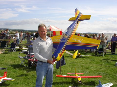
Me with Yak 54, photo courtesy of Geoff.

There were some nice aircraft to be seen at the show including a Stirling bomber, a deHavilland Mosquito and a Spitfire. A few jets put in an appearance with a Rookie, Kangaroo, Boomerang and an F16 flown very realistically by its skillful pilot. The electric slot was well over subscribed so the time allocation was doubled, electric gliders and slower craft first, followed by the faster EDF (Electric Ducted Fan) jets and other fast craft. That included me with the Pico-Jet.


video

A 180 panoramic

video

deHavilland Mosquito built and flown by Roger Kellow

Rogers Mozzie developed a problem during flight in that the undercarriage failed to lock down, but was able to recover from the situation and landed safely. Well done Roger.

Also impressive was a helicopter built by Kim Johns. Now helicopters leave me cold, I just can't get interested yet I feel compelled to watch in case it starts heading this way in an uncontrolled manner. But this was different. Modified and developed to accept a gas turbine, it was flown expertly by Mark Milne and performed just like a full sized helicopter. Even the sound and smell was the same. I'm told its the only one of its kind in the world - very impressive.

Sunday, 1 August 2010

I've had it running...!

...on both cylinders! Driving a 16" x 8" Master Airscrew propeller, and its too small. I've found it labours when it gets hot, so I think the pistons may be expanding, reducing the clearance in the bore. Its not been up to maximum revs as I'm still trying to find the best carburettor settings.
I can confirm the pistons have expanded whilst hot as there are shiny areas on the sides where friction has occurred. I set them up in the lathe and machined off a minimum amount, just enough to clean the sides. The rear bearing had just started to break up, this is a very small bearing at 3mm id x 6mm od x 2.5mm tk. Part of the metal dust cage had come out and some balls were missing, so I removed the what was left and replaced it with a spare. Now in the middle of reassembly. Should have it running again soon.
Off to Cornwall this coming weekend, but I don't hold out much hope of having it ready in time. There's too much work to do on the aircraft (Ultimate Biplane).

Monday, 26 July 2010

Not much left to do

Two holes to be drilled and tapped M1.6 in the bottom of each conrod and then the shells have to be made. Like the small ends, the big end shells are made from Phosphor Bronze. Two flat pieces are soft soldered together, held in a four jaw chuck and drilled (under size at this stage) on the joint. Then the outside diameter is turned to size and parted off. Warm gently to melt the solder and split the shells. Fit them in the big ends and tighten with the M1.6 screws, then set up on the mill and bore the big ends to size. Job done. Then its a matter of fitting it all together and seeing if the engine runs.

To give you an idea of the size, the distance between centres is 29.0mm.


Conrods with small end bearings fitted

Sunday, 18 July 2010

Nearing completion, but its a lot of tedius work

The crank shaft is almost finished, its been hard work as only small cuts at a time can be taken so as not to strain the setting. Its only held between centres in the lathe and if a tool were to pick up it would be disaster. As it is I'm very pleased with it. I need to reduce the weight a little and I've been studying some pictures of the Saito twin cylinder crank shafts and the balance weights have been shaped as a semi diamond on both sides ie where the counter balance weight would be. So I'm going to do the same.


You can see what I mean by the diamond shape...

I need to cut the same on the other side.

Monday, 12 July 2010

A Jet event at Westonzoyland

This was by invitation only and some pilots from the South East area Arrived on site for the weekend to "have a go" at flying from tarmac for a change. Everyone enjoyed themselves and there were no accidents or incidents. Normal Club flying activities continued as usual and the whole event went very well.


video

Friday, 9 July 2010

Some engineering at last

I've shelved the earlier crank shaft and decided to manufacture it a different way. This is how its done... a picture paints a thousand words, so here's a video.

video

Sunday, 20 June 2010

Spent the day flying

A cold wind from the North but it slowly warmed up as the day went on. The wind increased in strength and became gusty making flying conditions difficult as landings had to be cross wind. Just after 13:30hrs and I was the only one there after a good crowd earlier. Jim and Ian turned up with their jets later and the wind calmed a little and direction changed to the North West.


video


I really must get on and do some engineering...

Thursday, 13 May 2010

Thats it for a while!

I case you're wondering what been happening, I've been doing this!

Saturday, 24 April 2010

Another Crankshaft Failure

Yes, it failed again. This time it twisted slightly which meant the pistons didn't reach top dead centre at the same time, and the central crank web was rotating eccentrically in the crank case. This also meant the valve timing had slipped and the pistons were just hitting the valves of one cylinder. Luckily no damage was done, and now I've decided to manufacture a one piece crankshaft and the material arrived this week. Its a good job I made the crank case with a bulge in both sides as I'm going to need that internal volume for the much larger two-part big ends of the conrods. The material is an alloy steel, EN16T which is a tough steel, good with torsional strength. The down side of all this is that (as I mentioned earlier) I have to make two new conrods with a split big end and a split bearing. This bearing is made by soft soldering two pieces of phosphor bronze together and turning the bearing as one piece, then heating it up to melt the solder to form the two big end shells.
To give you an idea of the size, the cutter in the photo is 6.0mm diameter.

Crankshaft during remanufacture


Saturday, 10 April 2010

Best day for flying so far this year

Wall to wall hazy sunshine and light winds from the East. I thought it best to go today as the weather for tomorrow (Sunday) is breezy. Took the Pico-Jet, Sunbeam and the Yak and actually plucked up the courage to fly it. Had an engine cut shortly after take off, despite extensive pre-flight testing. The next flight was OK, but I had to stop to video this:-

video

Ians F16 is always an impressive display.

Two flights with each aircraft today, and I brought them all home in one piece - a very satisfying day.

Thursday, 1 April 2010

No April Fool

So this blog is about yesterday. (Wednesday 31st March 2010).


I've managed to re-assemble the KT120fsT and fit it to the fuselage of the Ultimate. I packed it all into the car and took it to work because at 19:00hrs the factory hooter goes off and I shout "Yaba Daba Doo"! (Flintstones connection) and then its time for a quick sprint over to the George Inn at Middlezoy to enter the Sedgemoor Clubs' Craftmans Cup. This is a chance to see what club members get up to in the cold dark Winter months.


A fine array of models had been built among them an Augusta helicopter, a Hawker Typhoon, a Corsair, and a Kyten. All very nicely finished, and of course its good to get together and have a natter.

2010 to be engraved

The Craftmans Cup 2007
Ketro KT54fs


The Craftmans Cup 2010
Ketro KT120fsT

Right! Whats next? How about a KTxxxfs7R? Hmmm, maybe??? What do you think?

Sunday, 28 March 2010

A new Central Crank Web and Big End Journals

On examination of the old assembly it appears the screw pin location hole was drilled and reamered on the p***. I don't know how I managed that, hence the resulting stress fracture. So, back to the drawing board to make a new one.


Jig set up for silver soldering the big end journals into place.


The new Central Web complete with Big End Journals

The journals are too long at the moment and will have to be cut to length to enable fitting between the front and rear crank webs.

I removed the shaft from the gear box because the bearing was lumpy, but it worked fine after I'd taken it out, so I cleaned it all up and noticed the shaft was bent. This could be the cause of the lumpyness, so shaft straightened and re-assembled into housing, it now works fine again.

Monday, 22 March 2010

Disaster!

I tried to fire up the KT120fsT today, and with very poor results. I managed to get it firing on one cylinder and occasionally it attempted two, but that is as far as things went. It all ended in tears when suddenly things came to an abrupt halt. I couldn't turn the crankshaft through a full 360, there was a stop preventing it going any further. Time to pack it all in and have some tea.

Broken crank pin

After tea I began dismantling the engine and it wasn't long before I discovered the crank pin on the central web had severed. I've also noticed the other pin in the web is loose. I must have done a poor soldering job there. Nothing else in the engine is damaged although the bearing in the gear box housing is a bit lumpy. I think I will change it.

A sorry sight

Sunday, 21 March 2010

Nearly finished

Yes, its almost ready to be fired up. Just a few odds and ends to finish off. Loads done today, I was hoping to position the carburettor on top of the engine, but there isn't quite enough space inside the cowling so plan "B" takes effect and the carb is mounted under the engine mount, between the exhausts.


View of the front underside

The carb is mounted with a 4.5mm offset. This is to compensate for the differing lengths of delivery tube. (They are different due to the 9.0mm cylinder offset.) The 4.5mm offset makes the mixture transit distance equal to both port and starboard cylinders.

Temporary fitting to the firewall


View of the rear with mount removed to show delivery tubes

The delivery tube system is made from 10mm micro bore tube and two standard elbow fittings. These fittings were modified to remove the solder ring and to add lightness. The two joints either side of the carb are butt joints. All the joints on the delivery tubes are silver soldered and there is a spigot silver soldered to the main part which extends into the carburettor manifold and the aluminium adaptor is glued to the spigot using Loctite 603 oil tolerant retainer. The carburettor is held in place using two M3 grub screws.

I can hear it running already!


Saturday, 13 March 2010

Made light work of more progress

Placed some strategic holes in the base plate to add lightening. They were designed for position and size, in other words not randomly placed.


Lightening holes (Not lightning holes)

I also made the exhaust pipes, large in diameter to muffle the bark. Aluminium inserts are pressed into each end of a stainless steel tube and the assembly is screwed to the cylinder head using an M3 socket cap head screw.

Exhaust stacks fitted


I've just looked back through my blogs and discovered that I started building this engine late in 2008

I went flying today as the forecast was good and with light winds. 'Tiz different when you get there, it was good earlier but the wind got stronger for the North West and by lunch time it was really cutting and Ipacked up and went home. Not before flying the Sunbeam and the Pico-Jet, and on the second flight with the Pico-Jet the prop parted company with the motor. All the bits flew off and scattered on the runway - time to land.

Phil was there with his Funtana. Look at the kit he's got to charge the batteries. That's not all, there's also a generator to power it all up.

No less than FOUR chargers


video

Phils Funtana

video

Exit left

Sunday, 7 March 2010

Engine Mount and First Trial Fitting

Started and finished the engine mount, and fitted it to the Ultimate to see how well it fits. The pictures tell more:-


Bags of room inside - Could've built a bigger engine


Exposed, showing the mount.


6mm dia. base, 8mm dia. spacers tapped M4 both ends


4 Degree angle


The original holes in the firewall are drilled at a 4 degree angle. This is to accommodate a large two stroke engine with a larger diameter cylinder and designed to fully enclose it so that unsightly holes don't need to be cut in the cowling. The KT120fsT needs to be horizontally mounted so the plate needed to be adapted.

Base is made from cast plate for lightness


So far it weighs 670 grammes including the mount, thats 1lb 7.5oz in old money. Not bad for a home build 24cc twin. There's a bit more to add, carburettor, manifold and delivery tubes, and exhaust pipes.


Monday, 1 March 2010

Things are beginning to get exciting...

Getting very close to the day when I can put some fire in its belly. I have to say, I'm very pleased with the way its turned out so far, there's been some difficulties, but I've designed my way out of them. All that's left to do now is make a pair of exhausts, the inlet manifold, mount the carburettor and make an engine mount suitable for the Ultimate Bi-plane.

Here's some pix:-

Gearbox cover detail


Starboard cylinder head close-up


Prop driver assembly fitted


Full view of the rear (top)


Underside